Alfa Laval SHE LTL
Introduction
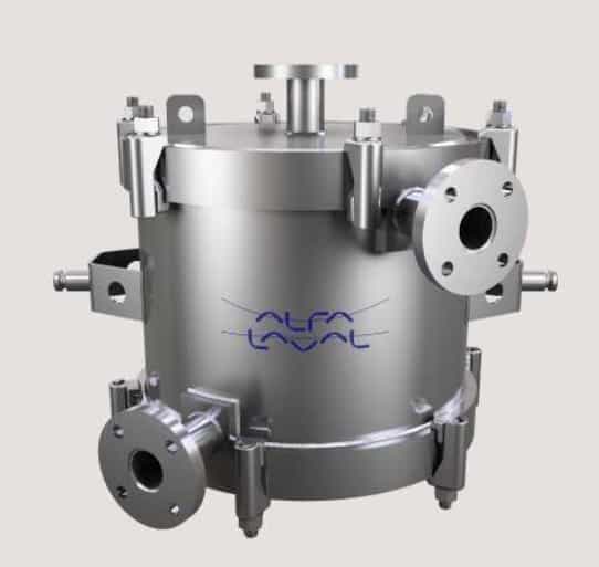
Engineered for liquid-to-liquid duties, the Alfa Laval SHE LTL is
a spiral heat exchanger with curved channels to provide
optimum heat transfer and flow conditions for a wide variety of
fluids. This spiral heat exchanger range offers a broad
spectrum of standard models with a wide variety of diameters
and heat transfer surface areas and can be used to handle
fouling fluids at medium pressures.
Applications
The Alfa Laval SHE LTL range is suitable for heating, cooling
and heat recovery in applications where there is a high risk of
fouling and where minimized operational downtime for
cleaning is crucial.
Their high heat transfer efficiency often makes them suitable
for replacing shell & tubes or other types of heat exchangers
where fouling risk or down time for cleaning are important.
Benefits
• Drastically reduced fouling thanks to the single channel design with its self-cleaning effect
• Easy inspection and mechanical cleaning (hydro-blasting) of the heat transfer surface
• Minimal operational downtime thanks to the longer intervals between cleaning and the ease of putting the unit back into operation after cleaning
• Highly efficient heat recovery thanks to true countercurrent flow
• Compact and flexible design that can be installed horizontally or vertically
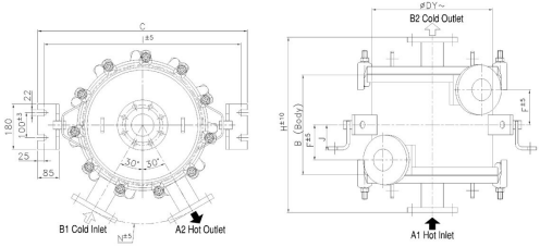
Working principle
The Alfa Laval SHE LTL spiral is made of two concentric spiral flow channels in which the media are in full counter current flow. The hot medium generally enters at the centre of the unit and flows from the inside outwards to exit at the periphery. The cold fluid enters normally at the periphery and flows towards the centre, thereby achieving counter flow. Counter current flow combined with optimal flow conditions in both channels obtains higher heat transfer coefficients than in many other types of heat exchangers. Close temperature approaches and temperature crosses are easily achieved.
The single channel design reduces drastically fouling and eliminates bypassing. Unlike multiple pass heat exchangers in which partial clogging redirects the flow through the remaining
open channels, the velocity in the single channel spiral increases until deposits are scrubbed away
Technical data
Maximum Allowable Working Pressure (with full vacuum)
Model 100 (212) 200 (392) 300 (572) 400 (752) °C (°F) 2S 12 (174) 10,5 (152) 9 (130) 6 (87) barg (psig) 2L 12 (174) 10,5 (152) 9 (130) 6 (87) barg (psig) 4S 10,5 (152) 10,5 (152) 9 (130) 6 (87) barg (psig) 4L 10,5 (152) 10,5 (152) 9 (130) 6 (87) barg (psig) 8S 10,5 (152) 10,5 (152) 9 (130) 6 (87) barg (psig) 8L 10,5 (152) 10,5 (152) 9 (130) 6 (87) barg (psig) 13S 10,5 (152) 10,5 (152) 9 (130) 6 (87) barg (psig) 30L 10,5 (152) 10 (145) 8,5 (123) 6 (87) barg (psig)
Design according to ASME VIII div.1 and to PED
Minimum design temperature: –40°C (–40 °F)
Other design conditions may be available on request.
Standard materials
Heat transfer surface 316L
Shell 316L except covers in Carbon steel lined with 316L Gaskets Nitrile-bonded fibre
Flange 316L (EN 1092-1 PN16 / ASME B16,5 150 lbs)
Heat transfer area Dy H Spacing Nozzles Weight (empty) Model m2 (ft2) mm (inch) mm (inch) mm (inch) mm (inch) kg (lbs) 2S 2 (21) 425 (17) 500 (20) A=B= 5 (0.2) 50 (2) 185 (408) 2L 2,1 (23) 425 (17) 600 (24) A=B=8 (0.3) 50 (2) 195 (430) 4S 4,3 (46) 480 (19) 600 (24) A=B= 5 (0.2) 50 (2) 285 (628) 4L 4 (43) 480 (19) 700 (27) A=B=8 (0.3) 80 (3) 290 (639) 8S 8 (86) 540 (21) 700 (27) A=B= 5 (0.2) 50 (2) 420 (926) 8L 8,8 (95) 540 (21) 925 (36) A=B=8 (0.3) 80 (3) 460 (1014) 13S 13,5 (140) 645 (25) 800 (31) A=B= 6 (0.24) 80 (3) 680 (1500) 30L 29,3 (315) 825 (32) 1400 (55) A=12 (0.5)/B=10 (0.4) 100 (4) 1380 (3042)